|
It is most important to
verify all linkage and levers are installed without
binding and the linkage opens to full throttle and is
allowed to close to the Idle Speed Screw. This is the
number one and two reasons for tuning errors, improper
linkage installations and over tightened linkage nut,
causing binding in the linkage assembly.
The Individual Runner
Carburetors, DCOE, have individual Idle jets and mixture
screws for each barrel. They also have an additional
air bleed screws and lock nuts. This is not used for
idle adjustment or idle quality. The settings for
these screws should be closed.
Standard DCOE Settings:
Speed screw ¼ to ½ turn in
after contact with lever maximum.
Mixture Screw 1 turn out
from lightly seated.
“Lean Best Idle”
Procedures
After confirming the
linkage allows the throttle lever to seat against the
Idle Speed Screw. Back off the Idle Speed Screw, then
turn the screw in until it contacts the throttle lever
and turn it in ½ turn. Turn in the Mixture Screw in
until it “LIGHTLY” seats, then back it out 1 full turn.
Loosen the 8mm wrench size nuts on the “air bleed”
screws, turn in the air screws until it seats then
tighten the nut.
a.
Start the engine, it will run slow and like a
tractor. As long as it will stay running, the idle speed
is not important at this point.
b.
First, turn in the mixture screw until the engine
runs worse, then back out the screw ¼ turn at a time.
The engine should start to smooth out. Continue to back
the screw out ¼ turn at a time until the screw does
nothing or runs worse. Then turn it back in to the point
where it ran best. You want to tune the engine by sound.
Adjust each mixture screw to the best, fastest and
smoothest running point. Do this procedure with each
mixture screw.
c.
Now you may adjust the Idle Speed Screw. It
should be sensitive and only require ¼ turn in or out to
achieve the idle speed you like.
d.
These Carburetors are commonly used in pairs,
this makes the synchronization important, be sure to
bring the high flowing Carburetor down to the low flow
Carburetor. Then bring them both up to “proper” Idle
speed. The Idle Speed Screws are not opened more than
½ turn in.
e.
After synchronizing multiple Carburetors,
reconfirm steps b. c. & d.
“Simple Rules for
Calibration”
If your mixture screw is
out more than one turn like 11/2 turns then your idle
jet is too lean, go up one half size on the Idle jet.
If you mixture screw is
not out one full turn, something like only 1/2 turn out
from seated then your Idle jet is too rich, go down one
half size on the idle jet.
This is all based on
the important fact that your speed screws are
not open more than ½ turn if they are then that is
also an indication that you have a lean Idle circuit.
You are cheating by opening the throttle plates and
exposing additional progression holes in the transition.
Pump
By-pass Valve:
The pump by-pass valve is designed to allow fuel into
the pump circuit and when depressed, by-pass a
percentage (hole on the side of the valve) of the fuel
delivered to the accelerator pump nozzle/jets. We have
included the zero by-pass valve in our jet kit. This
will deliver all of the available fuel to the engine and
not by-pass fuel back to the fuel bowl. This will
increase the duration and volume of the pump shot with
the original pump jets. To decrease the duration and
increase the fuel volume we have included in our jet kit
the larger 55 pump nozzle/jets. This is for maximum fuel
delivery from the accelerator pump circuit. The
accelerator pump by-pass valve is located in the bottom
of the fuel bowl, one is required per carburetor.
DCOE
Adjustment controls
Tuning & Adjustment
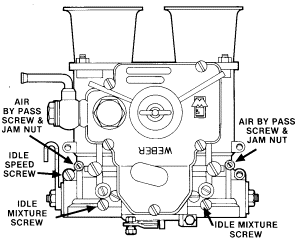
1.
Critical!
Be sure for initial carburetor set up all air by-pass
screws should be in closed position. These are not
commonly used in standard carburetor adjustment.
2.
Set the idle speed screw at ¼ to ½ turn in after
contact with throttle lever. When doing multiple
carburetors all linkage should be disconnected. All
Carburetors should be bench adjusted to same setting.
3.
Set the idle mixture screw to one turn out form
lightly seated. When checking the seated position to
make only light contact with seat, aggressive seating
will damage needle and seat of carburetor,
4.
Start
engine as long
as engine starts and runs do not set up idle
speed first. First adjustment if possible should be to
find smoothest idle with each mixture screw on all
carburetors. Some prefer to do one barrel of each
carburetor then come back and do the second barrel
5.
After preliminary lean
best setting of idle. Check carburetors for
synchronization. Commonly done by checking lead or front
barrel of each carburetor.
6.
You will always want to
bring high flow carburetor down to match the low flow
carburetor. If this cannot be done you will need to
recheck bench assembly for binding throttle in high flow
Carburetor. Once you have matched both carburetors you
will need to set the idle to the desired idle speed
setting. This will be done by adjusting both Carburetors
up or down the same amount and re checking for
synchronization.
7.
Make one last check of
lean best (smoothest running position) idle on all
mixture screws one last time.
8.
Best idle should
end up with the mixture screws at or near one turn off
seat. Check rule of thumb for idle jet selection in
REDLINE basic idle adjustment instruction.
|
|
|
Part No. 99006-110
|
|
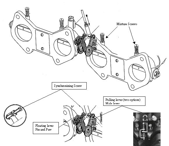
NOTES
-
You will
need to install levers on carburetors before
installing them on manifold.
-
You have a
choice of two lever styles be sure to
determine how you want to connect cable to
linkage. If you do not have a ball socket
style cable then you will need to drill out
(remove) ball from lever. Use part 99005
357-cable holder in place of ball.
-
Be sure to
use caution when installing levers, DO NOT
OVERTIGHTEN CARBURETOR THROTTLE SHAFT NUTS
this will cause binding of shaft and
possibly damage to the throttle plates and
the body of carburetor.
-
Install
cable support bracket to 4 screws on bottom
of carburetor body (fuel chamber). Install
on the same carburetor with the Pulling
lever (male lever).
-
Run exposed
cable through cable housing support bracket
and to your pulling lever on carburetor.
Remember you have three hook up options.
|
|
|
|
19550-174 40 DCOE
|
|
19600-060 45 DCOE |
|
|
 |
| Float Settings |
| Early Style brass float 8 to
8.5mm (at radius) |
| Late style plastic float
12.5 to 13mm at extreme tip of
float
|
| All settings are gasket to
float |
|
| Float setting notes
|
| 1. Fuel pressure is critical
to float spillage 2.5 to 3 lbs.
|
| 2. For aggressive off-road
use float drop should be limited
to 1 to 1.5 mm max drop of tap
for float needle |
|
Down load hi-res version |
|
| KEY CALIBRATED PARTS
|
| 8) 79503-xxx Needle & Seat
|
| 9) 41030-005 Brass Float
(early style) |
| 9) 41030-034 Nitrofil Float
(late style) |
| 15)
73401-xxx Main fuel Jet
|
| 11) 77401-xxx Main Air
corrector Jet |
| 16) xxxxx-xxx Idle Jet Idle
jet has both a size and f
number designation call for part
no |
| 57) 76801-xxx Accelerator
pump Jet |
| 43) 79701-xxx Accelerator
by-pass Jet |
|
|
The Part Number for
the Jets with .xxx after the part number means this
is the size you want.
The sizes are all 3 digit. If you want a 120 main it
is .120 If you want a 50 Idle it is .050
See Exploded Diagrams of each carb for more
detail:
Baseline jetting of new Weber carbs when they are
shipped from us.
| |
DCOE |
|
Main Jets |
 73401.xxx 73401.xxx
|
|
Air Jets |

77401.xxx
|
|
Idle Jets |
 F8 or F9
F8 74821.xxx
F9 74822.xxx
|
|
Emulsion Tubes |
61450.xxx
|
|
Choke Tubes |
40mm 72302.xxx
45mm 72116.xxx
|
|
Aux Venturis |
See Diagrams |
|
Pump Bleeds |
79701.xxx
|
|
Pump Jets |
76801.xxx
|
|
Needle and Seats |
79503.xxx
|
| |
|
|
Filter Assembly # |
Dimensions / Part # |
| 99217.472 |
4.5"x 6.75" x
1.875" High |
| Replacement
Element |
99400.291 |
| Replacement
Clips |
99217.001S |
 |
|
| |
|
| 99217.473 |
4.5" x 6.75"
x 2.625" High |
| Replacement
Element |
99400.292 |
| Replacement
Clips |
99217.000S |
 |
|
DCOE Series Carbs. 40mm - 45mm - 48mm
|
Filter Assembly # |
Dimensions / Part # |
| 99217.517 |
4.5"x 6.875"
x 1.75" High |
 |
|
| |
|
| 99217.525 |
4.5" x 6.875"
x 2.5" High |
 |
|
| 99217.532 |
4.5" x 6.875"
x 3.25" High |
 |
|
|
40 and 45
DCOE Clamp On Velocity Stack Filters
|
45 DCOE and
48 IDA Snap On Velocity Stack Screen
Filters
|
RamFlo Style AIr Filters for
DCOE and DGEV
|
|
|
|
|
|
For 40 DCOE
and 45 DCOE
|
|
|
|
![]() CLICK HERE TO DONATE TO HELP FUND THIS SITE!
CLICK HERE TO DONATE TO HELP FUND THIS SITE!









 73401.xxx









![[Most Recent Quotes from www.kitco.com]](http://kitconet.com/images/quotes_7a.gif)